
Colecovision No-Cut Video Connector Box
1. Introduction
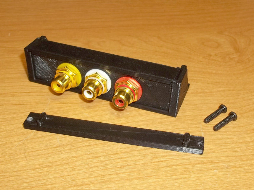
This box enables the mounting of common video/audio connectors without having to cut or drill holes in your Colecovision console shell- what was once a permanent proposition is now completely reversible with little chance of damaging aging and brittle plastic.
This item is available with different faceplates depending on the type of connectors you plan to install on your system, RCA jacks, S-Video or a blank plate so you can drill your own holes for Lumacode or RGB output.
While this guide is intended to be a thorough installation of the connector box, installation of the video mod itself is not the scope of this instruction set and ultimately, all aspects of the installation is the responsibility of the customer, so take caution that you don't damage anything.
2. The Vents
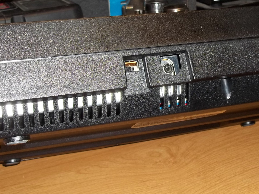
The box attaches at the rear of the console, mating with the ventilation slots in the back. Overheating isn't a concern here since there isn't a lot of airflow around the RF modulator location anyway, and the new box doesn't obscure all of the vents on this side.
You will need to open the Colecovision housing at this point. To disassemble your console it's recommended you consult a guide elsewhere, but you want to unscrew all screws from the underside/bottom, then carefully pull the top half off since it is attached to a front plate that holds the bottom half in.
3. Placement
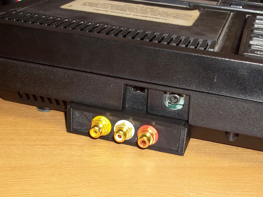
This is how the new video connector box should sit against the ventilation slots, it's angled to mate with the underside slope of the console shell so it should be apparent how things will sit.
Once the Colecovision's been opened up remove the mainboard and RF shielding and set them aside.
4. Back Brace
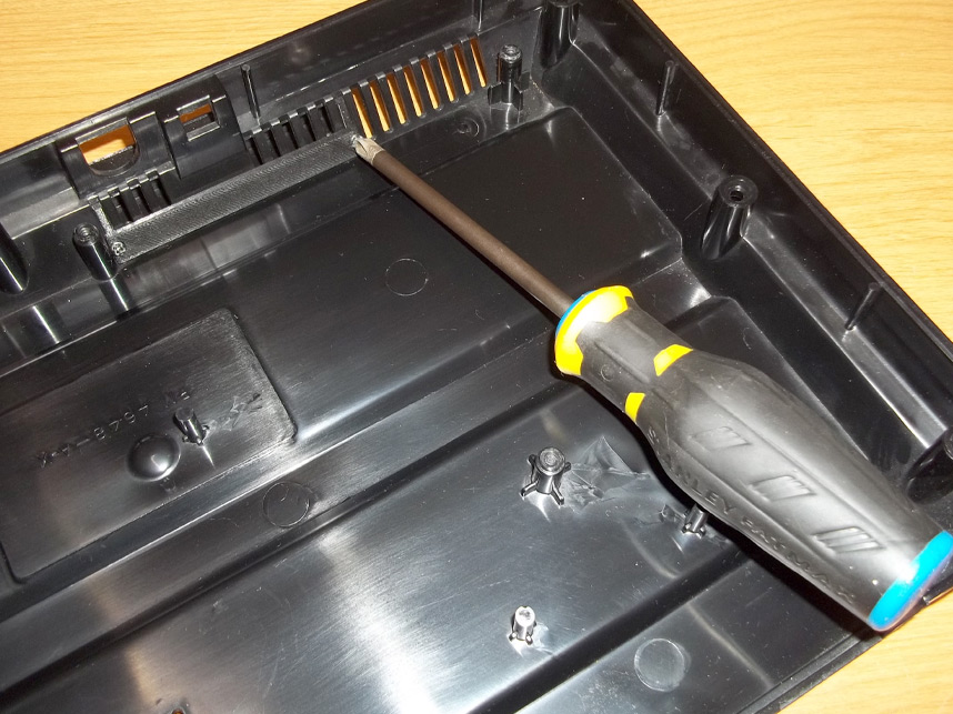
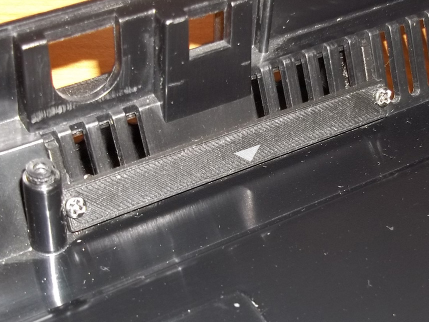
The box is anchored into place with a flat brace piece which is screwed in with two included machine screws. These screws go in at a slight angle to match the angle of the console shell's own slope.
Note! You should not do this until you've run your wiring, which is covered a little later in this guide. This is just to show you in advance how the box is locked in.
5. Back Brace Continued
The brace is keyed so that it seats into the ventilation slots on the opposite side of the connector box. Note that there will be a triangle on the flat side to indicate how it's oriented to the bottom of the console shell.
This is so there's sufficient clearance for the bottom half of the RF shielding to sit once you return the mainboard into place. Before you go to close up the console shell, make sure that your RF shielding is not obstructed from sitting flat by this back brace, otherwise it may be screwed in improperly.
6. Wiring
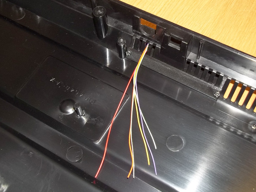
Wiring should be routed to your connectors (and through one of the open available ventilation slots) before you screw down the back brace.
Be mindful that you don't pinch the wiring as you're screwing down the back brace either, and make sure that your wire is long enough to reach the circuitry that you need it to.
After you test everything to your satisfaction, you should be able to close the console back up.